Server-grade processors: A few notable server-grade processors are given below:
1. Processor types: Intel Core i7 (900 series), Intel Xeon (35xx, 36xx, 55xx,56xx series), Intel Celeron
2. Intel Itanium 9300-series
3. Intel Xeon 6500/7500-series
4. AMD Opteron 6000
5. AMD Phenom II, Athlon 2, Sempron, Opteron 3xxx
Multi-threaded Processor: A multi-threaded processor executes the instructions in parallel, but shares the other resources like registers. A multi-processor system, on the other hand have independent support units. Therefore, other things being equal, a multi processor system is more efficient than a multi-threaded processor based computer. Further, a multi-threaded processor is a single chip where as a multi-processor system will have several independent processor chips
Socket types: Socket 1366, also called LGA1366 or Socket B, is a Land Grid Array (LGA) socket used by the latest generation of server-class Intel Core i7 and Xeon microprocessors. The socket supports triple-channel or six-channel DDR3 SDRAM memory controller with frequencies up to 3.2 GHz. The socket 1366 along with the socket 1156 superseded socket 775.

DMA enables the data to be written to or Read from the Memory directly. The processor is almost free to execute other instructions as programmed during the DMA process.
The following are the important features of multiprocessing:
1. Normally, multiprocessing (SMP) does not require separate memory for each processor. The processors share the same computer resources.
2. The Operating System software has to be written specifically to support multiprocessing.
3. Theoretically, there is no upper or lower limit on the processors requirement. Normally at least 2 processors are required to utilize the strengths of a multiprocessing operating system. Some computers support as many as 64 CPUs in multiprocessing architecture.
4. Applications that are developed keeping in view the multiprocessing architecture can benefit from the same.
5. In a multi-processor system, the CPU speeds and the L2 cache must match.
Some important points to remember:
Troubleshooting resource problems:
1) Pages/sec: Pages/sec is a memory object that indicates how often data is written to and read from the paging file. The normal limit is about 6 pages/sec. For example, a reading of 21 pages/sec indicates insufficient memory. Note that the paging file usage can to up to 80%.
2) Processor utilization contraint: Processor time utilization has a maximum allowed limit of 80%. Fpr example, with a processor time utilization of 96%, you may consider enhancing the processing capacity by upgrading the processor or adding a second processor.
3) Heating issues in small form factor computers and laptops: CPU throttling is a technique used in some computers to run the CPU at a reduced speed than the rated speed. As a result, the processor consumes lesser power and also produces less heat. This may be advantageous in small form factor computing devices such as laptops and mobile phones.

Running a CPU at a speed higher than the rated speed is called overclocking.
Enabling a single processor to execute two or more streams of instructions at the same time is called Hyperthreading
Overlapping of steps involved in processing CPU instructions is called Pipelining.
4) Troubleshooting using Event Log: The events log in a server contains the exact nature of the problem encountered when installing or initializing the application. After identifying the exact problem, an administrator may proceed to further remedial action.
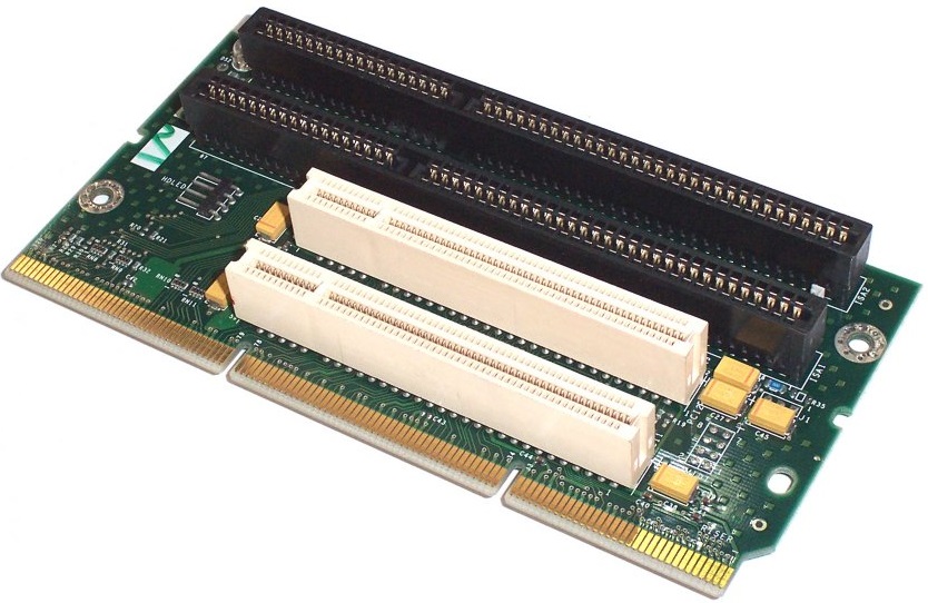
Riser card: A riser card is a board that plugs into the system board and provides additional slots for adapter cards. Because it rises above the system board, it enables you to connect additional adapters to the system in an orientation that is parallel to the system board and save space within the system case. Please see the figure below:

Riser cards are often used to allow adding expansion cards to a system enclosed in a low-profile case where the height of the case doesn't allow for a perpendicular placement of the full-height expansion card. Riser cards allow the addition of expansion cards, such as video and graphic cards, to a system that doesn't allow for perpendicular placement of the expansion cards. Riser cards plug into and rise above the system board, while providing additional expansion card slots. Riser cards enable the connection of additional cards in a parallel orientation to the system board, as opposed to perpendicular, which conserves space within the system case.
BIOS/UEFI: UEFI (Unified Extensible Firmware Interface) is a standard firmware interface for PCs designed to replace the BIOS.
Notable advantages are given below:
1. Better security - The biggest benefit of UEFI is its security over BIOS. UEFI can allow only authentic drivers and services to load at boot time, making sure that no malware can be loaded at computer startup. Microsoft implemented this feature to counter piracy issues in Windows, while Mac has been using UEFI for quite some time now. Secure Boot works by requiring a digital signature of boot loaders which should require digital signature by the Kernel.
2. Faster startup times and resuming from hibernation - Since UEFI is platform independent, it may be able to enhance the boot time and speed of the computer.
3. Support for drives larger than 2.2 terabytes (TB): BIOS uses the Master Boot Record (MBR) to save information about the hard drive data while UEFI uses the GUID partition table (GPT). The major difference between the two is that MBR uses 32-bit entries in its table which limits the total physical partitions to only 4. Each partition can only be a maximum of 2TB in size, while GPT uses 64-bit entries in its table which dramatically extends the support for size possibilities of the hard drive.
4. Support for 64-bit firmware device drivers - UEFI provides support for 64-bit firmware device drivers.
5. It does not have to replace BIOS. UEFI can sit on top of the traditional BIOS and act as an interface between it and the operating system. Like BIOS, it presents a standardized view of the hardware to the operating system, allowing operating system makers to build on top of it and have their OSes work on a variety of motherboards.
Memory (RAM) Types:
ECC: ECC is mainly used for servers and other mission critical applications that requires extra security and stability. Non-ECC are for regular use like for gaming and home pc. ECC rams are a bit slower since it works with extra steps that prevents errors and are a bit expensive in most cases. You can use both in a Non-ECC motherboard, but you have to use an ECC supported motherboard to use the ECC feature of the ECC RAMs.
Double data rate (DDR): DDR is clock - doubled SDRAM (covered later in this section). The memory chip can perform reads and writes on both sides of any clock cycle (both the up and the down), thus doubling the effective memory executions per second. So, if you're using DDR SDRAM with a 600 MHz memory bus, the memory will execute reads and writes at 1200 MHz
By performing two transfers per cycle of a quadrupled clock, a 64-bit wide DDR3 memory module can achieve a transfer rate of up to 64 times the clock speed in megabytes per second (MBps). In addition, the DDR3 standard permits chip capacities of up to 8 GB.
Typical speeds of DDR3 memory are given below:
Memory module type: DDR3-800
Speed: 6400 MBps
Standard: PC3-6400
Memory module type: DDR3-1600
Speed: 12,800 MBps
Standard: PC3-12800
12,800 MBps may be arrived from the clock speed of 1600MHz as below:
Take a clock rate =1 unit.
Two transfers per sec (on both raising and falling edge): 2x1
Clock rate quadrapled: 2x4=8
64-bit data bus can transfer 8 bytes (64/8) at a time.
Therefore, the transfer speed would be: 8x8 or 64 times the clock speed.
So, multiply the clock speed of 1600MHz with 64 (8x8) = 102,400 bits per second or 12,800 mega bytes per second (MBPs)
DDR4 SDRAM is the abbreviation for "double data rate fourth generation synchronous dynamic random-access memory," the latest variant of memory in computing. DDR4 chips support transfer rates between 2133 MT/s (million transfers per second) and 4266 MT/s. By comparison, DDR3 technology supports only up to 800 to 2133 MT/s. This significant memory transfer boost will enable hardware developers to produce DDR4 chips with more powerful processors. This new memory also uses less power, 1.2 Volts compared to 1.65 Volts of DDR3 chips.
SIMMs: SIMMs need to be installed in pairs. SIMM stands for Single In-line Memory Module
Dual inline memory modules (DIMMs) have two rows of pins and twice the contact with the motherboard than older single inline memory modules (SIMMs). DIMMs differ in the number of conductors, or pins, that each particular physical form factor uses. Some common examples are 168-pin (SDR RAM), 184-pin (DDR, DDR2), and 240-pin (DDR3) configurations. DIMMs can be installed one at a time.
Bus Types:
Important features of PCI 2 bus are given below:
1. PCI-X 2.0 is a higher speed version of the PCI X ( more specifically PCI-X 66 and PCI-X 133) standard.
2. PCI X 2.0 provides for two new speed grades: PCI-X 266 and PCI-X 533, offering up to 4.3 gigabytes per second of bandwidth
3. PCI 2 is up to 32 times faster than traditional PCI bus speed
4. Doubles and quadruples PCI-X bandwidth.
5. Full hardware and software backward compatibility (i.e. compatible with PCI, and PCI X).
6. Uses the same form factor, pin-outs, connector, bus widths, and protocols.
7. PCI-X 2.0 offers enhanced system reliability. ECC support has been added, providing automatic single-bit error recovery and double-bit error detection.

The throughput offered by 133MHz, 64-bit bus is 133X(64/8) Megabytes per sec or 1064 MB per sec.

The most probable cause for hard disk thrashing is that the RAM may need to be increased. Check for too many page file accesses, which may be resulting in disk thrashing.
Adapter teaming: Adapter teaming is also known as port aggregation. It is useful when you need to increase the bandwidth over the network media. High bandwidth utilization is experienced with bandwidth intensive applications such as video streaming, or downloads. Adapter teaming provides load balancing, and network redundancy. You need to assign the same IP address for both network cards when implementing adapter teaming. Adapter teaming provides increased bandwidth, and network redundancy. You need at least two network cards to implement adapter teaming. On the other-side of the network cables, you need a switch that can support adapter teaming.
The following are the features of adapter teaming:
1. In adapter teaming, single IP address is used. Even though there multiple adapters, all of them use a single IP address.
2. Adapter teaming provides fault tolerance. Even if one of the adapter connections fail (say due to cable cut), then the network connection still exists through the second adapter.
3. Adapter teaming requires at least two network adapters on a server to implement.
4. If you use adapter teaming on the server side, and connect the cables to a hub, then the resulting solution may not improve the available bandwidth. You need a switch that supports adapter teaming (or load balancing) on the other side of the network. A hub inherently can support adapter teaming.

