Metro Ethernet (also called Ethernet WAN) point-to-point link is works at layer-2 of the OSI reference model. The service providers network acts like a big Ethernet switch. Metro Ethernet typically uses fiber Ethernet for connectivity to the ISP (or the Service Provider).
Given below are the most widely used standards for Metro Ethernet (also called Ethernet WAN):
1. 100BaseLX10 - 100Mbps with a range of 10km
2. 1000BaseLX - 1Gbps and a range of 5km
3. 1000BaseZX - 1Gbps with a range of 100km
4. 10GBaseLR - 10Gbps with a range of 10km
5. 10GBaseER - 10Gbps with a range of 40km
Note: UTP cabling is not very suitable for Metro Ethernet due to distance limitations and fiber Ethernet is most widely used.
Ethernet WAN may provide different topologies,
1. Point-to-point: Here any two customer premise equipment exchange frames as if they are connected by a leased line. Ethernet Line Service (E-line) corresponds to point-to-point topology
2. Full Mesh: Here, any customer device (connected to the ISP) may communicate with any other device (of the customer) directly via the Ethernet WAN service provided by the Service Provider. Ethernet LAN Service (E-LAN) corresponds to Mesh topology
3. Hub and Spoke: Point to Multi-Point, etc.: Here, a central site can communicate with remote sites directly, but remote sites can not communicate directly. Ethernet Tree Service (E-Tree) corresponds to Hub and Spoke topology.
Virtual Private Wire Service (VPWS) is used for E-line service, and Virtual Private LAN service (VPLS) is used for E-Lan service.
In similar terms, EoMPLS uses MPLS for internally routing the customer information, where as the customer sees only the Ethernet frames.
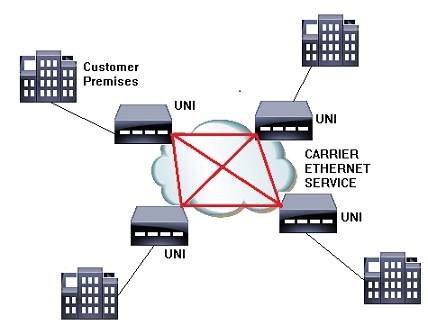
Example of E-LAN Service

UNI: User Network Interface.
The network configuration given in the figure is simplified representation of an E-LAN service. As you can see, every node will be able to communicate with every other node in the network (full mesh configuration) via the service providers Ethernet LAN service. On the other hand, if the full mesh configuration is not available, then it typically represents a partial mesh or a hub-n-spoke network configuration.

Note that all the routers at the customers' end would be in the same subnet. The communication takes place at layer-2 across the carrier network. Ethernet frame leaves the customer premises at one point, and the same Ethernet frame enters the customer premises at the other point. What happens inside the SPs network is transparent to the user.

