IANA (Internet Assigned Numbers Authority) is the organization under the Internet Architecture Board (IAB) of the Internet Society that oversees the allocation of Internet Protocol addresses to Internet service providers (ISPs). ICANN (a non governmental organization) has now assumed responsibility for the tasks formerly performed by IANA. ISPs in turn allot IP addresses to small companies, and businesses.
The IPv6 protocol defines a set of headers, including the basic IPv6 header and the IPv6 extension headers. The following figure shows the fields that appear in the IPv6 header and the order in which the fields appear.

The following list describes the function of each header field.
Version – 4-bit version number of Internet Protocol = 6.
Traffic class – 8-bit traffic class field.
Flow label – 20-bit field. Flow label is a new field in the IPv6 header. A 6-to-4 tunnel works similarly to a manual tunnel, except that the tunnel is set up automatically. 6-to-4 tunnels use IPv6 addresses that concatenate 2002::/16 with the 32-bit IPv4 address of the edge router, creating a 48-bit prefix.
Payload length – 16-bit unsigned integer, which is the rest of the packet that follows the IPv6 header, in octets.
Next header – 8-bit selector. Identifies the type of header that immediately follows the IPv6 header. Uses the same values as the IPv4 protocol field.
Hop limit – 8-bit unsigned integer. Decremented by one by each node that forwards the packet. The packet is discarded if the hop limit is decremented to zero.
Source address – 128 bits. The address of the initial sender of the packet.
Destination address – 128 bits. The address of the intended recipient of the packet. The intended recipient is not necessarily the recipient if an optional routing header is present.
The extension header may include the following:
Hop-by-Hop options
Destination options
Routing (specifies intermediate routers that the route must include forcing an administratively defined path)
Fragment (Used to divide packets that are too large for the maximum unit (MTU) )
Authentication and Encapsulating Security Payload (ESP)
IPv6 hosts should support the following addresses:
Assigned global unicast and anycast addresses (2000::/3)
Loopback address (::1/128)
Link-local address (FE80::/10), autoconfigured
All-nodes multicast addresses (FF01::1 and FF02::1)
Solicited-nodes multicast addresses (FF02::1:FF00:/104 and appending the last 24 bits of the corresponding unicast or anycast address of the device)
Any other assigned multicast addresses (in the range FF00::/8)
Routers should additionally support at least the following:
Subnet-router anycast address
All-routers multicast addresses (FF01::2, FF02::2, and FF05::2)

The following are true about IPv6 address format
1. The total length of IPv6 address is 128 bits
2. The first 48 bits of the IPv6 global unicast address are used for global routing
at the Internet Service Provider (ISP) level.
3. 16 bits (after the first 48-bit global unicast address) are used for subnetting, allowing organizations to subdivide their network
4. Multicast addresses are in the range FF00::/8.
5. In an IPv6 network, a host can auto configure its IP address without the help of a DHCP server.
Basic rules:
1. ":" in every 2 bytes.
2. heading 0s in each block can be omitted
3. "0: all zeros in between :0" can be written as "::"

IP helper addresses: IP helper addresses forward a client broadcast address (such as a DHCP or BOOTP requests) to a unicast or directed broadcast address. Helper-address is required due to the fact that routers do not forward broadcasts. By defining a helper-address, a router will be able to forward a broadcast from a client to the desired server or network. There can be more than one helper-address on a network. The helper-address must be defined on the interface that receives the original client broadcast.

Note that "ip unnumbered" command is used to enable IP processing on a serial interface without assigning a specific IP address to the interface.
To enable routing of IPv6 packets, we need to enable IPv6 on a router by using the command :
Router(config)# ipv6 unicast-routing
To enable IPv6 on an interface, use the command :
Router(config-if)#ipv6 enable
To add an IPv6 address to an interface : ipv6 address <address>/<prefix> [link-local] [eui-64]
Exampls: ipv6 address 2001:100:1::1/64
To leave the interface unnumbered : ipv6 unnumbered eth 0/0
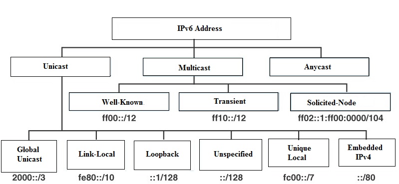
IPv6 Packet Types: IPv6 uses three types of communication: Unicast (one-to-one), Multicast (one-to-many), and Anycast (one-to-closest). The concept of Broadcast messaging is tied with the IPv4 protocol and is no longer valid in IPv6. There is no such thing as Cryptocast messaging. Figure below shows the these three types of communications

Unicast 6to4 addresses (2002::/16) are used to communicate between two IPv6/IPv4 nodes over the IPv4 Internet. A 6to4 address combines the prefix 2002::/16 with the 32 bits of the public IPv4 address of the node to create a 48-bit prefix - 2002:WWXX:YYZZ::/48, where WWXX:YYZZ is the colon-hexadecimal representation of w.x.y.z, a public IPv4 address.
The Maximum Transmission Unit (MTU) is the largest number of bytes an individual datagram can have on a particular data communications link.
All IPv6 networks must support an MTU size of 1280 bytes or greater. This is because IPv6 routers do not fragment IPv6 packets on behalf of the source. IPv6 routers drop the packet and send back an ICMPv6 Type 4 packet (size exceeded) to the source indicating the proper MTU size. The IPv6 addressing scheme supports 128 bits. IPv4 and IPv6 networks can exist simultaneously. It is possible to tunnel IPv6 packets through IPv4 networks. IPv6 is downwards compatible with IPv4.
Tunneling is used when two hosts using IPv6 want to communicate through a region of IPv4.
When a packet enters and passes through the IPv4 region, IPv6 packet is encapsulated in IPv4 packet.
The IPv6 packet leaves the capsule when it exits the region of IPv4.
The source and destination fields are set to IPv4 addresses of tunnel endpoints.
The IPv4 Protocol field within the IPv4 header is set to 41 to indicate an encapsulated IPv6 packet.
When using the tunnel, firewalls and/or routers using packet filtering must be configured to allow IPv4 Protocol 41 packets to be received and forwarded.
Using a protocol translator between IPv6 and IPv4 allows direct communication between hosts speaking a different network protocol. One of the benefits of NAT-PT is that no changes are required to existing hosts, because all the NAT-PT configurations are performed at the NAT-PT router. Customers with existing stable IPv4 networks can introduce an IPv6 network and use NAT-PT to allow communication without disrupting the existing network. NAT-PT is not recommended for a scenario in which an IPv6-only network is trying to communicate to another IPv6-only network via an IPv4 backbone or vice versa
AnyCast:
Anycast addresses can be used only by a device, not a host
Anycast addresses must not be used as the source address of an IPv6 packet.
The anycast address is identified by a prefix concatenated by a series of zeros (the interface ID)
2001:db7:A00:1::1/64 is an ipv6 unicast address, where as 2002:db7:c058::/128 is an example of ipv6 anycast address. Note that in anycast ipv6 address prefix is concatenated by a series of zeros.
Typical commands that enable ipv6 routing are:
RouterA>enable
RouterA#configure terminal
RouterA(config)#ipv6 unicast-routing
IPv6 Multicast Addresses used by different routing protocols:
RIPv6 : FF02::9
OSPF speaker: FF02::5
OSPF DR and BDR: FF02::6
Multicast Address Node Local::
FF01:0:0:0:0:0:0:1 or FF01::1 All Nodes Address
FF01:0:0:0:0:0:0:2 or FF01::2 All Routers Address
Link Local:
FF02:0:0:0:0:0:0:1 or FF02::1 All Nodes Address
FF02:0:0:0:0:0:0:2 or FF02::2 All Routers Address
FF02:0:0:0:0:0:0:D or FF02::D All PIM Routers
The main transition mechanisms are Manual, Teredo, 6 to 4, ISATAP Tunneling, and NAT-PT. GRE is another tunneling technology that is similar to the other tunneling technologies, and used for IPv4 to IPv6 tunneling and vice versa.
GRE: IPv6 traffic can be carried over IPv4 GRE tunnels using the standard GRE tunneling technique. The tunnels are not tied to a specific passenger or transport protocol, but in this case, carry IPv6 as the passenger protocol with the GRE as the carrier protocol and IPv4 or IPv6 as the transport protocol. The primary use of GRE tunnels is for stable connections that require regular secure communication between two edge routers or between an edge router and an end system. The edge routers and the end systems must be dual-stack implementations.
NAT-PT: The term NAT-PT stands for Network Address Translation and Protocol Translation. NAT refers to translation of an IPv4 address into an IPv6 address and vice-versa and PT stands for the translation of the IPv4 packet into a semantically equivalent IPv6 packet and vice-versa. NAT-PT allows native IPv6 hosts and applications to communicate with native IPv4 hosts and applications, and vice-versa. A NAT-PT device resides at the boundary between an IPv6 and IPv4 network.
6 to 4: 6to4 enables dual-stack devices to transmit IPv6 traffic across an IPv4 backbone via 6to4 relay servers without the need to manually configure tunnels. Similar to ISATAP, the tunneled IPv6 traffic is encapsulated in IP protocol 41 packets on the IPv4 network. 6to4 may be used by an individual host, or by a local IPv6 network, but does require the use of a public IPv4 address.
ISATAP: ISATAP (Intra-Site Automatic Tunnel Addressing Protocol) is an IPv6 transition mechanism meant to transmit IPv6 packets between dual-stack nodes on top of an IPv4 network. Unlike 6over4 (an older similar protocol using IPv4 multicast), ISATAP uses IPv4 as a virtual nonbroadcast multiple-access network (NBMA) data link layer, so that it does not require the underlying IPv4 network infrastructure to support multicast.
Teredo is a transition technology that gives full IPv6 connectivity for IPv6-capable hosts which are on the IPv4 Internet but which have no direct native connection to an IPv6 network. Compared to other similar protocols its distinguishing feature is that it is able to perform its function even from behind network address translation (NAT) devices such as home routers.
Multicast addresses from FF01:: through FF0F:: are reserved, well-known addresses. To identify all nodes for the node-local and link-local scopes, the following multicast addresses are defined
FF01::1 (node-local scope all-nodes address)
FF02::1 (link-local scope all-nodes address)
To identify all routers for the node-local, link-local, and site-local scopes, the following multicast addresses are defined:
FF01::2 (node-local scope all-routers address)
FF02::2 (link-local scope all-routers address)
FF05::2 (site-local scope all-routers address)
Mapping IP Multicast address to MAC address
The high order 25 bits of the 48-bit MAC addresses are fixed and the low order 23 bits are variable. The high order 9 bits (out of total of 32 bits) of the IP address are not used for mapping into the MAC address. The lower 23 bits are mapped to lower 23 bits of MAC address.
So the multicast address 224.252.6.24 becomes 01-00-5E-7c-06-18. To use the 23 low order bits, the first octet is not used, and only the last 7 bits of the second octet is used. The third and fourth octets are converted directly to hexadecimal numbers. The second octet, 252 in binary is 11111100. If you drop the high order bit, it becomes 1111100 or 124 (in decimal), or 7c (in hexadecimal). For the next octet, 6 in hexadecimal is 06. For the last octet, 24 in hexadecimal is 18. Therefore, the MAC address corresponding to 224.252.6.24 becomes 01-00-5E-7c-06-18.
A dual-stack router can receive requests from both IPv4 and IPv6 clients on the same interface. This provides a smoother transition between the two protocols.
1. Automatic 6to4 is a point-to-multi point tunneling method, where the tunnel destination is determined from the border router IPv4 address facing the IPv4 network.
2. The border routers that delimit the 6to4 tunnel must support IPv4 and IPv6 and are not configured in pair.
3. Automatic 6to4 can be used to connect two IPv6 networks as well an IPv6 host to an IPv6 network.
4. IPv6 network is treated as NBMA link.
5. The IPv4 embedded in IPv6 is used to find the other end of the tunnel.
6. Border routers create a tunnel on a per packet basis to other IPv6 Border router.

